Shut-down and dismount
In the control room:
- Type shutdownobssys notcam in an
xterm. Wait until the whole data acquisition system has been shut
down completely.
- Switch off power to the NOTCam shutter monitor ("the buzzer")
which is on the wall behind the Lisa
terminal.
In the dome:
- Switch off power both to the camera controller and the motor
controller. Disconnect the power cable from the 220V outlet
in the adapter.
-
Disconnect the network cable from the 3Com
network switch in the adapter. Also disconnect the shutter monitoring
cable from its slot in the motor controller rack (the cable is marked
NOTCam (Spare), and you need a screwdriver), and coil
it nicely inside the hole in floor.
- Take off the extra weights (45 kg) and dismount the arm which is
fixed to the NOTCam flange by 3 screws.
- Before placing the trolley under NOTCam you need to remove the 2 grey
bolts that are in the middle of each group of three.
The remaining 4 grey bolts must be loosened.
- Make sure that the Helium hoses are on the left side of NOTCam (as
viewed from the door) before placing the trolley under the instrument.
You should not need to lift the hoses over or under the instrument.
- Place the NOTCam trolley under the instrument and lift it all up.
- Take out those 4 grey bolts you have loosened. Remove the remaining yellow
and red bolts. For the two red bolts, you need an extra key to be found
behind the entrance door. Leave all bolts in the plastic bag attached to the
trolley. Note that by January 2016 there are 2 broken threadholes in the
adapter plate on the StanCam side.
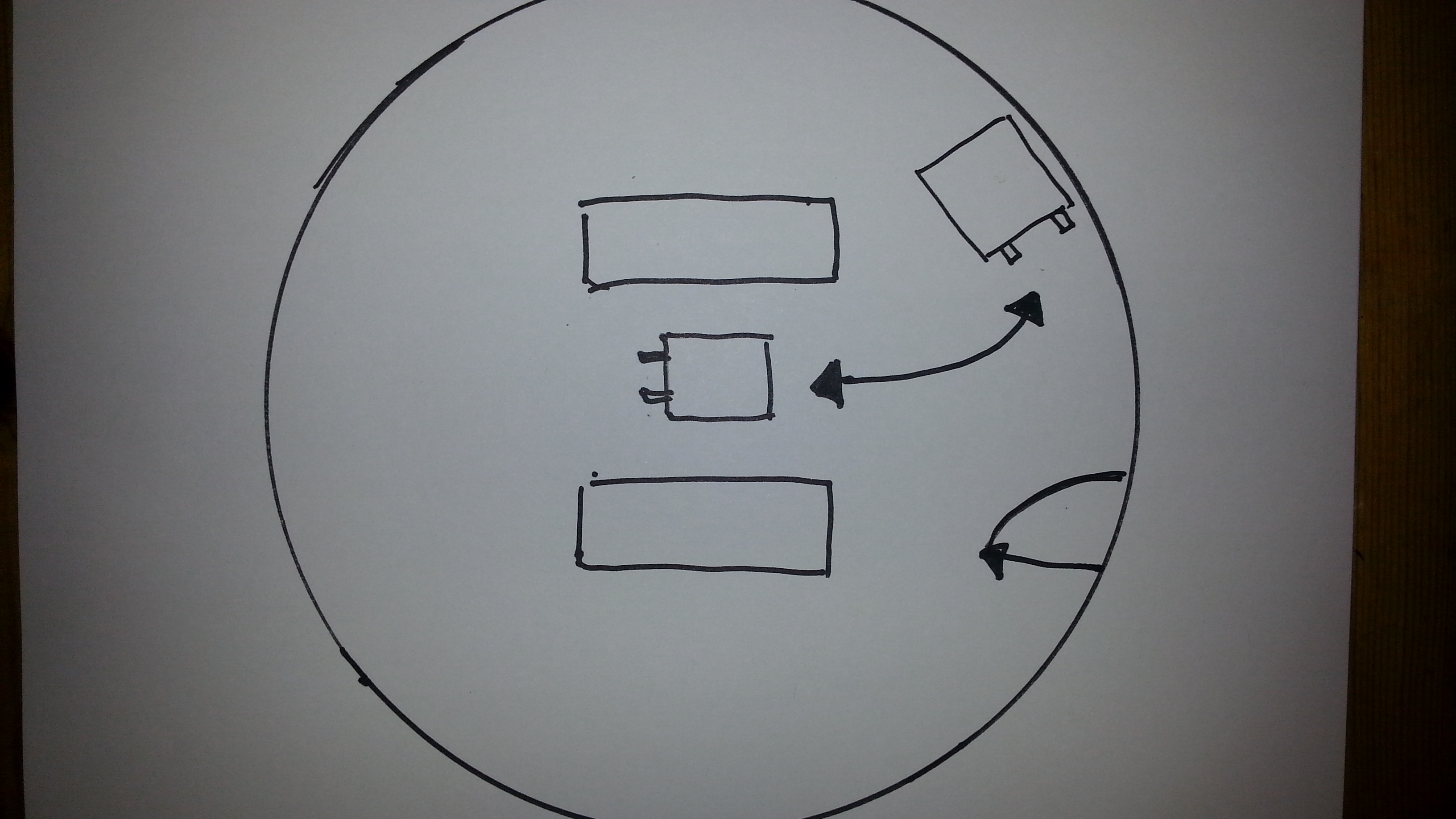
- Take the lift down. Make sure that you rotate NOTCam the correct way when
moving it to
the park position. Rotate NOTCam the shortest way, i.e. about 100 degrees
to have the LN2 fill/vent tubes towards the entrance door.
Seen from above this is counter-clockwise. See schematic sketch and
the orientation of the LN2 fill/vent tubes:
If NOTCam is also turned the correct way when mounted, we hope to avoid
adding loops on the hoses.
- Put the lid above the NOTCam entrance window, and move NOTCam to its
storage place. The LN2 fill/vent tubes are now sticking out towards the
entrance door.
NB! Handle the PTR hoses with care and avoid any sharp bends!
Lift up the hoses towards the ceiling.
- Connect the orange network cable to the network socket on the dome
wall.
- Connect the power cable to a 220V outlet.
- Power on the motor controller!!!.
NB! Without this we get no temperature readings from NOTCam and will
not know if it warms up!
- Power also on the detector controller. This is new since 2013 and due
to an on-going long-term monitoring of the reset-level.
- Put the black cover over the instrument but do not cover the motor
controller. Use the rope provided to secure the cover.
- Make sure the PTR is running without problems and check that the cooling
water temperature is within 10 to 30 degrees (can be checked in
the
TMS, sensor 367, or directly on the digital display on top of the
PTR compressor in the machine room).
|